Technical Solution for a Wheelset Measuring Stand
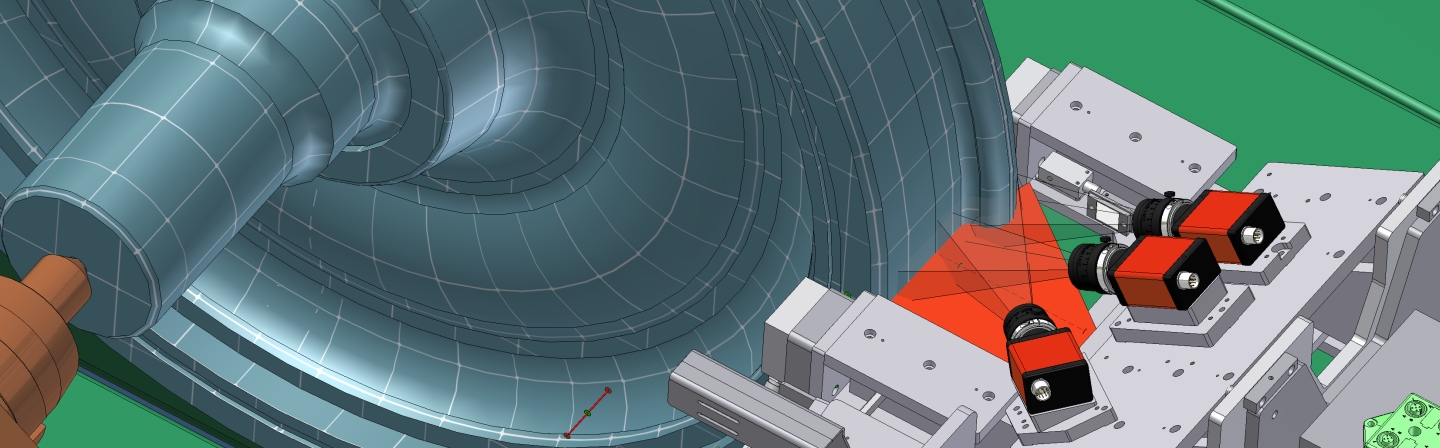
A fully automatic measuring stand consists of components for wheelset handling and the actual measuring unit. The wheelset handling system inserts wheelsets in and removes them from the measuring position and moves them to scan data. Optical line and point sensor clusters that operate based on the principle of triangulation are employed to scan data. Five sensor clusters operate in one common coordinate system and each digitizes relevant areas of the surfaces of wheel profiles, wheels and shafts. The sensor can be adjusted radially to accommodate different wheel diameters.
Data is evaluated in software modules modified for specific tasks. Wheelset and wheel profile coordinate systems are ascertained in a first step and the geometry parameters are computed in a second step. A computerized system controls the motion systems, acquires data through sensor clusters, and evaluates and logs data.
Results of Measurement (in Compliance with Deutsche Bahn AG Guidelines)
Wheelset dimensions
- Distance of inner wheel flange faces (AR)
- Distance of inner wheel flange face to the center of the wheelset shaft (AR1, AR2 and/or c, c’)
- Measuring circle diameter (dM)
- Radial runout tolerance in the measuring circle planes (H)
- Axial runout tolerance of the wheel disks (G)
- Diameter and radial runout tolerance of the wheelset shaft (F)
- Gauge size (SR)
Wheel profile dimensions
- Flange thickness (Sd)
- Flange height (Sh)
- Cross dimension of the flange flank (qR)
- Flange and/or rim width (BR)
The system is flexibly upgradable to measure other parameters (e.g. for disk brakes or drive components).
An accredited calibration lab has certified this wheelset measuring stand’s performance.