OptoInspect3D scanning technology for optical quality inspection

We supply methods, tools and licensable software-libraries for your 3D scanning systems

Speed, robustness, automation capability and a suitable measurement principle are the key properties of in-line metrology. The OptoInspect3D technology package developed at Fraunhofer IFF provides you a modular toolkit for implementing 3D scanning systems for specific applications.

OptoInspect3D includes methods and tools to design, configure and simulate optical scanning systems. Functions for rapid, timed and automatic 3D measurement data interpretation and geometrization are another key component. OptoInspect3D additionally includes tools to calibrate and adjust systems configured for specific applications from several sensors and motion components.

Our OptoInspect3D scanning technology can be used in any industry and is suitable for assorted process control and quality inspection tasks, such as inspection of geometric tolerances for dimension, shape and position and assembly and completeness verification. OptoInspect3D has been in use for over ten years and is continuously being refined.

OptoInspect3D Inline: software library for 3D point cloud processing

OptoInspect3D Inline is a program library with highly efficient algorithms to process three-dimensional point clouds and geometries. Its distinctive features are top performance, robust methods with certified accuracy and ease of integration in custom applications, sensors and equipment. Flexible licensing models and, if necessary, customization or application-specific upgrades of functions ensure the software library is versatile. The accompanying graphical development and test environment permits easy testing of algorithms.

© Fraunhofer IFF

Functions

Registration and alignment

Measurement data usually have to be registered before they can be compared with a CAD model or a reference measurement (golden sample). The OptoInspect3D-Inline library includes all the functions needed for this. Registration can be calculated between two point clouds or between a point cloud and a CAD model in the form of a triangle mesh. Several point clouds can also be simultaneously aligned and merged into one object. Then, a subsequent distance calculation between scan and model data shows whether the data sets fit together.

Filtering and preprocessing

Scanned point clouds frequently have to be preprocessed or filtered to allow sophisticated analysis. The functions provided for this enable removing outliers from the scan data and spatially segmenting smoothing and homogenizing point clouds. Features, such as curvatures or point densities, can be identified and normal vectors of the measurement data can be calculated for realistic visualization.

Best-fit geometric primitives

A frequent task in sophisticated 3D data processing is the fitting of geometric primitives in measurement data and the subsequent interpretation of differences. The OptoInspect3D Inline library supports a variety of such primitives, including lines, planes, circles, ellipses, spheres, cylinders, cones and tori. They can be approximated using various minimization criteria. Along with the least square displacement method (Gauss), approximations of the minimum zone (Chebyshev), minimum bounding (bounding geometry) and maximum inscribing (Pferch) are available.

OptoInspect3D Inline library features

  • Numerous algorithms for the analysis of 3D measurement data and CAD comparison
  • Support of various operating systems (Windows, Linux) and architectures (x86_64, ARM)
  • Can be run on SoC systems, such as Raspberry Pi and NVIDIA Jetson
  • Universal Type-C-compliant interface without external coupling
  • Top performance through efficient data structures and multicore support
  • Processing of large numbers of points
  • PTB-certified accuracy
  • Development and test environment with OpenGL-based visualization
 

3D measurement data processing

Discover our OptoInspect3D Inline solution for highly efficient processing of three-dimensional point clouds and geometries.

OptoInspect3D Inline demo version

Test the demo version of our OptoInspect3D Inline solution and learn about all the modules, functions and interfaces in the HTML documentation.


Get the free demo version

View the HTML documentation

OptoInspect3D Sim: simulation and view planning for optical Inspection systems

As the variety of manufactured products grows, demands on the flexibility optical inspection systems’ function are increasing too. The use of robots or the additional integration of positioning axes make it possible to record sensor data flexibly. At the same time, data interpretation also has to be flexibly adapted to new product specifications. Our OptoInspect3D Sim software library provides a solution to these challenges.

Sensor simulation for synthetic reference data generation

OptoInspect3D Sim employs a model-based approach to enable the planning and implementation of assorted inspection tasks with optical sensors. Whereas conventional optical inspection systems normally draw on predefined reference data and corresponding inspection algorithms for variance analysis, the model-based approach is significantly more flexible whenever there is a need to respond to frequent changes of inspection requirements. Consistent use of the item under test’s CAD data and a model description of the inspection system enables precisely predicting the readings expected in the to-be state in the form of synthetic measurement data. These can be image or 3D data that adjust automatically to any change to the design of the item under test.

Comparison of the measurement data of the item under test with the data generated by the simulation using suitable metrics eliminates renders manual adjustment of inspection algorithms unnecessary. The simulation is optimized so that it already delivers suitable data.

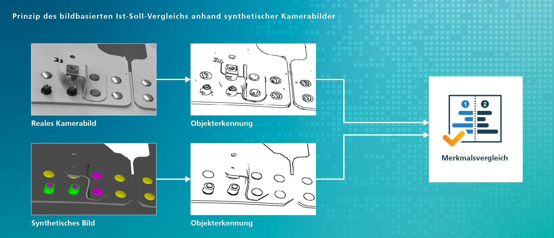
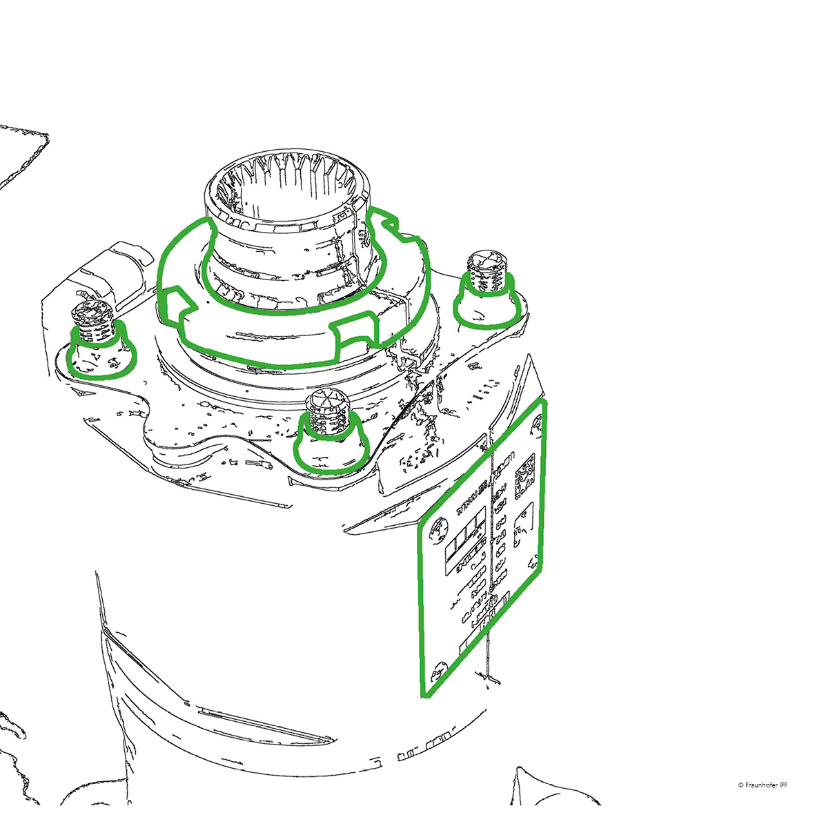
Edge filters can be used to compare the informational content of synthetic and real camera images, for instance. The items under test are segmented, extracted and compared in both images. Our model-based approach permits precise segmentation of the image region analyzed, direct simulation of the expected edges and thus a robust decision.

© Fraunhofer IFF
The principle of variance analysis of synthetic camera images.

Sensor simulation for view planning

An important task for flexible, for instance, robotic inspection systems is finding the ideal sensor position to precisely scan the desired quality features. Not only the visibility of the features to the optical sensor used but also its alignment to the product’s surface is crucial. This is the only way to meet scan conditions and prevent interference by adverse reflective properties.

OptoInspect3D Sim provides flexible and automatable view planning. Whenever the inspection task changes or new components are added, the corresponding path can be adjusted or created automatically.

© Fraunhofer IFF
Automatic view planning based on synthetically generate simulated measurement data.

Automatische Bewertung von Sensorposen anhand Messdatensimulation.

Widely varying inspection system configurations can be analyzed very quickly by varying the sensor’s position to the product as a function of the available degrees of freedom, the maximum sensing range and, if necessary, other conditions, such as collision avoidance. The selection of a reliable configuration enables automated quality assessment of the generated synthetic measurement data based on predefined criteria. Manual teaching of sensor positions is no longer necessary.

Automatisch ausgewählte Sensorpositionen für eine 3D-Messaufgabe.

Extensive practical tests usually cannot be performed for every product variant, either when configuring inspection systems or when operating them later. Our model-based approach in OptoInspect3D Sim delivers synthetic measurement data of the product regardless of its physical design. This enables drawing conclusions about the inspection system’s suitability for the intended use case. The inspection system can thus be designed and evaluated based on the simulation data before the item under test has even been manufactured.

OptoInspect 3D Sim library features

  • Software library for the simulation of synthetic measurement data to calculate appropriate sensor positions based on CAD data and sensor parameters (view planning and viewpoint selection)
  • Geometrically correct generation of synthetic measurement data for optical 2D, 2.5D and 3D sensors (e.g., camera, PMD, light sectioning and structured-light 3D scanning) including shading
  • Simulation and data interpretation with various metrics and strategies
  • Input: specification of sensor functions in the form of geometric and optical parameters and of the target object in the form of a CAD model
  • Output: synthetic measurement data and location-based assessment of the data quality based on surface features and reflectance
  • Top performance through full calculation in the graphics processing unit (GPU) and the use of advanced rendering techniques
  • Available as a library and as an environment with a graphical user interface
 

Simulating and designing optical inspection systems

Discover our OptoInspect3D Sim solution for easily designing and simulating optical inspection systems.

OptoInspect3D Calib: calibration of optical sensors and systems

An absolute measurement system is needed whenever a product’s geometric dimensional and shape tolerances ought to be inspected optically. This not only assumes the existence of calibrated individual sensors but also exact knowledge of the location of the individual sensors in space in relation to the target object. This makes it possible to transform the individual sensors’ measurement data into a shared coordinate system and identify geometric features in it, such as diameter or radial runout. The location of the scanning system components in space for a scanning system configured for a specific application must be determined in a one-time calibration and positioning procedure.

© Fraunhofer IFF

Our software library OptoInspect3D Calib provides system integrators and sensor and equipment manufacturers a method and software functions for automatically determining sensor positions and motion axes (sensor positioning and scanning) for systems configured for a specific application.

The principle of the positioning procedure is based on a model description of the scanning system and the specification of the model’s parameters by taking measurements on a calibration block.

Process chain for generating a 3D measurement data set exemplified by car rim.

OptoInspect3D Calib library features

  • Flexible procedure for calibrating a scanning system’s optical sensors and motion axes
  • Transformation of the individual sensors’ data into a shared coordinate system for absolute measurements
  • Traceability of the scan to a national length standard through reference measurement on an appropriate calibration block
  • Calibration supersedes fine adjustment of components (e.g., when replacing sensors)
  • Reproducible insertion of components is no longer necessary. The calibration procedure can be fully automated.
  • Suitable for laser range sensors, laser light section and structured-light 3D scanning sensors and camera sensors
 

Calibrating optical sensors and systems

Discover our OptoInspect3D Calib solution to calibrate and position your optical sensors and inspection systems precisely.