Inspection of Profile Dimension and Shape Tolerances
Profiled semi-finished products and structural profiles with a wide variety of cross-sections and dimensions are widely used in manufacturing. They are the base material for the design of many products. Profiled materials are normally rolled and drawn or extruded. In addition to shape and dimension tolerances of a profiled material’s cross-section, longitudinal parameters such as straightness and torsion are important criteria for the evaluation of product quality.
The Fraunhofer IFF has developed non-contact measurement technology for the inspection of dimension and shape tolerances of profiled materials, which facilitates quality inspection integrated in manufacturing. It inspects not only such parameters as straightness and torsion but also dimension and shape tolerances of a profiled material’s cross-section fully automatically.
The technology can be implemented in non-contact optical measuring systems modified for specific tasks, which can be integrated directly in a manufacturing line. Inspection results are delivered quickly, thus supporting direct process feedback and continuous quality inspection.
Measurement Technology
Profiled materials are inspected in two steps. First, relevant regions of the profile surface are digitized three-dimensionally. Second, the data is evaluated and the geometric parameters are determined:
Digitization
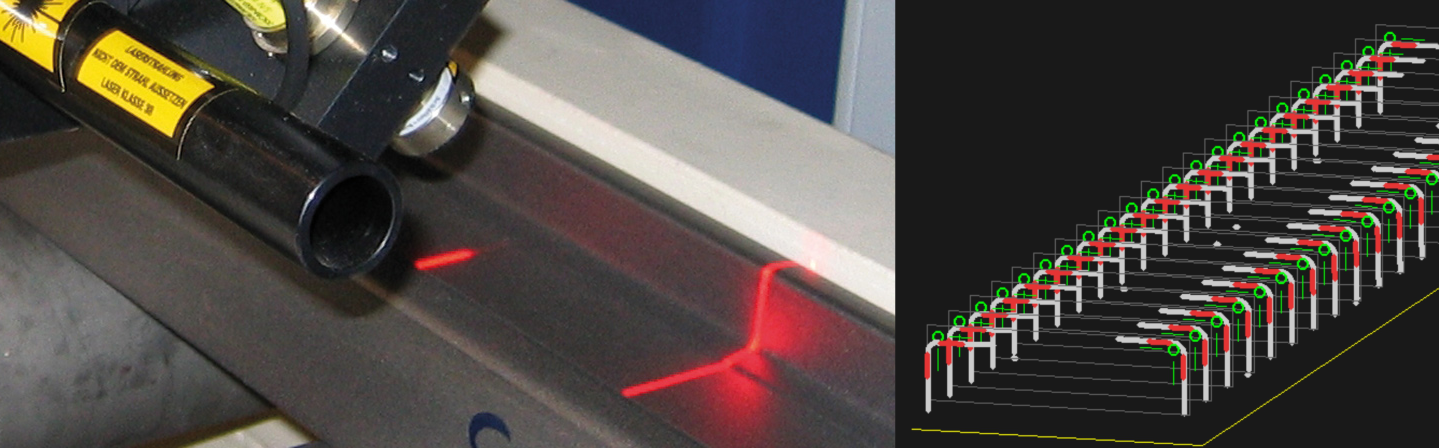
Laser light-sectioning is employed to digitize the surface of a structural element. Camera-laser arrays for light-sectioning sensors, which scan the surface of a structural element line by line, are configured as a function of the shape of the profile cross section Camera-laser arrays configured as light-sectioning sensors as a function of the shape of the profile cross section scan the surface of a structural element line by line. A linear unit moves the sensor unit by in the direction of the profile’s longitudinal axis. One profile cross section apiece is scanned in equidistant intervals.
Scanning Motion and Axis Error Correction
Since deviations directly enter readings, precise linear motion is important to the guidance of the sensor unit along the profile. Our solution dispenses with expensive high-precision linear guides by relying on a simple linear axis combined with an additional optical measurement system, which detects deviations from the ideal linear trajectory and thus corrects axis errors.
Measured Data Evaluation and Determination of Geometric Features
Measurements are evaluated based on 3D data as a sequence of profile cross sections along the profile axis. The profile cross sections are determined by transforming the data from individual sensors into a common coordinate system and a projection into the profile cross section plane. Afterward, approximation can identify geometric primitives of suitable reference geometric elements in the 3D data. Dimension and shape tolerances of the shape of a profile cross section can be computed from this data or shape tolerances such as straightness and torsion can be computed by analyzing reference geometric features along the longitudinal axis of the profile.
A variety of already implemented systems solutions have demonstrated this technology’s performance in industry.